The I/V-converter

1. Introduction

An I/V-convertor is intended to convert the current from a DAC (Digital Analog Convertor) into an analog voltage and to filter this signal to keep out the alias frequencies. Often these functions are separated into two stages: one for the conversion, and another for the low pass filtering. I will call them: 'the I/VC' and 'the lp-filter'. The current from the DAC (often 2.5 mA) is far from clean. Outside the audio frequency domain the aliases and rest-signals of digital origin with a wide frequency spectrum do exist. The input impedance of the I/VC should be constant and low (< 5 ohm) over the whole frequency range in question.
Both stages should perform without noticeable distortion (< 0.001 %).


The lp-filter eventually has to actuate the following audio system with about 3 volt at 0 dB.
Often op amps are used in both stages. At least the usage of an op amp in the I/VC is criticized: 'How could one put such a complex signal in a circuit with a vary high open loop gain?' It has to be clear that an op amp in this application must have a large GB-product.
The (12 dB/octave) slope of the lp-filter should start at 20 kHz and drop monotonic to -160 dB!
Before the circuits are put together, they will be simulated with MicroSim8, a more then ten years old SW-package on PC which satisfies. These simulations are presented here.

2. The I/VC

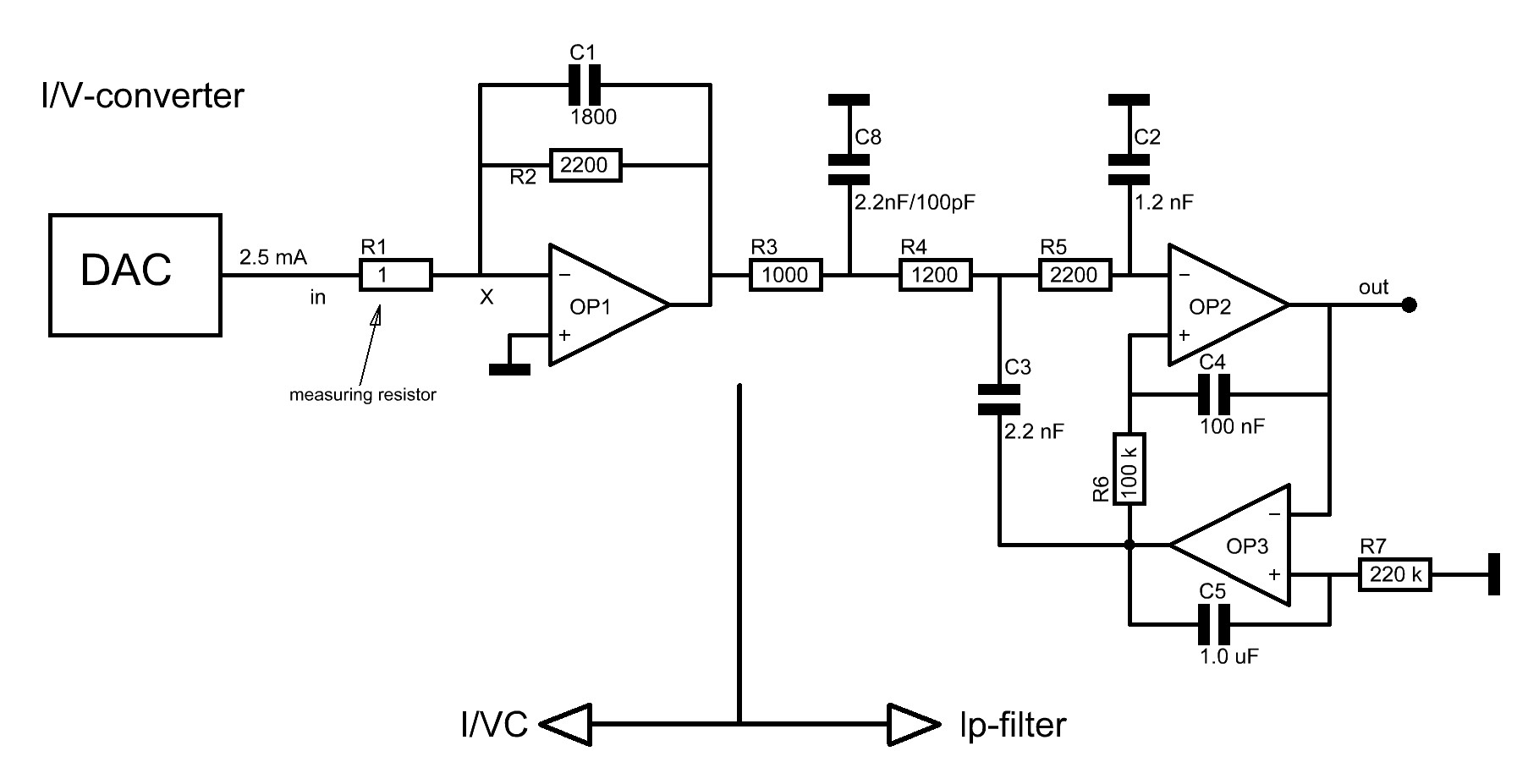
What about the high frequency components in the DAC-current? Cannot they be filtered out before entering high open loop gain stages? Cannot high open loop gain stages be avoided at all? Because of the low distortion figures and a reasonable low output impedance, at least the lp-filter does need feedback. Because of the prescribed low input impedance of the I/VC, it must start with an emitter- or source-input stage if no use is made of 'the virtual ground-circuit' with an op amp.


2.1   I/VC with discrete bipolars

The discrete I/VC-circuit with bipolar transistors (at the right) performs best if the second harmonics have been cancelled with the proper value of R1 and R2. The third harmonic however is still .04 %.
(R5 is used to get a first idea of the input impedance in the plots.)
The frequency response is excellent. The slope is even 12 dB/oct due to the extra 56 nF. R6 cannot be much higher than 100 ohm on penalty of more distortion. The output voltage is 0.25 volt (with a DAC-current of 2.5 mA) so that appending amplification of 20x is needed.

Plots of the I/VC with discrete bipolar transistors

  1. The frequency response (gain)
  2. The input impedance
  3. The distortion


2.2  I/VC with a FET

The discrete I/VC-circuit with ten times the FET J310 in parallel in GGS performs very well. The frequency response is excellent and the distortion is low. The circuit shown at the right is only for simula- tion purposes. Of course in practice the DC-level of the input should be 0 volt. This will be realised by biasing the gate.
As with the discrete bipolar transistors, some measures should be taken to get a better power supply rejection (PSR).
The power consumption (some 70 mA) is high to serve a low source-impedance. Instead of the ten J310's, one could look after a large FET (with cooling!).
A current transformer is another solution if the 'leakage induction' could be kept low enough. With one J310 a step up of 1 : 3 will satisfy. Apart from the difficulties constructing a good transformer (could an old MC-cartridge transformer be of help?), a transformer is sensitive to magnetic fields so at least with the mains transformer in the same box, this solution offers hum.

Plots of the I/VC with FET

  1. The frequency response
  2. The input impedance
  3. The distortion

2.3   I/VC with an Op Amp

If we stick to low distortion, we must resort to op amps. The question is: which op amp will perform best. The circuit diagram of an op-amp-I/VC is rather simple.
The circuit behaves as a virtual ground circuit, at least at low frequencies. The value of the feedback-resistor (R2 in the diagram above) can be rather high because of the large open loop gain of the op amp in question. With 2200 ohm, the input impedance will be


much smaller than 1 ohm, often some milli-Ohm. The combination
of R2 and C1 serves the first filtering (6 dB/oct.) and compensates somewhat the decreasing open loop gain as function of the fre- quency.
The output voltage of the I/VC is simply I-DAC x Z-feedback. In the audio domain this will be e.g.: 2.5 10-3 x 2200 = 5.5 V at 0 dB.

2.3.1   I/VC with an OPA648

The wide band, emitter-input current feedback, single op amp OPA648 is unity gain stable, with a
Unity Gain Bandwidth = 1 GHz,
an open loop gain = 55 dB, and
a Slew Rate = 1200 V/us.
Looking at the plots, one could notice that the input impedance of the virtual ground decreases in the range of 100 kHz to 50 MHz! In the audio range it is 130 mOhm, to decrease to about 25 mOhm at
1 MHz.
As could be predicted the 6 dB/oct slope runs monotonously down to 100 MHz. But, the distortion is to high (0.04%) because of the emitter-input configuration (see data sheet) of this op amp.


Plots of the I/VC with an OPA648

  1. The frequency response at in- and output
  2. The input impedance
  3. The distortion

2.3.2   I/VC with an OPA134

The ultra low distortion, FET-input, op amp OPA134 is
unity gain stable, with a
Unity Gain Bandwidth = 8 MHz,
an open loop gain 120 dB,
an output resistanse = 10 ohm, and
a Slew Rate = 20 V/us.
Its gain is large enough but it lacks bandwidth for this application. The input impedance starts from some m-Ohm at 10 Hz to 7 ohm at about 100 kHz already!


Plots of the I/VC with an OPA134

  1. The frequency response at in- and output
  2. The input impedance
  3. The distortion

2.3.3   I/VC with an LT1028

The ultra low noise, single op amp LT1028 is unity gain stable, with a
Unity Gain Bandwidth = 50 MHz,
an open loop gain >120 dB,
an output resistanse = 80 ohm, and
a Slew Rate = 15 V/us.
The expensive beautiful extra low noise LT1028 performs well in both areas: the distortion is unmeasurable low and the input impedance is extremely low at 10 Hz (nano-Ohm) and increases to
about 3 ohm at 100 kHz. The slope above 20 kHz is correct. The only remark is the change in input impedance, which simply could be solved with a 2 ohm shunt!


Plots of the I/VC with an LT1028

  1. The frequency response
  2. The frequency response with 2 ohm shunt at entry
  3. The input impedance
  4. The input impedance with 2 ohm shunt at entry
  5. The phase at in- and output
  6. The distortion

2.3.4   I/VC with an AD826

The dual op amp AD826 is unity gain stable, with a
Unity Gain Bandwidth = 50 MHz,
an open loop gain = 75 dB,
an output resistanse = 8 ohm, and
a Slew Rate = 350 V/us.
It simulates a little bit better than the LT1028. The slope is smoother. From the investigated circuits perhaps the best choice. The reason is its low output impedance: The input impedance can't be higher than the sum of the reactance of the feedback capacitor and the output impedance of the op amp.


Plots of the I/VC with an AD826

  1. The frequency response
  2. The frequency response with 2 ohm shunt at entry
  3. The input impedance
  4. The input impedance with 2 ohm shunt at entry
  5. The phase at in- and output
  6. The phase at in- and output with 2 ohm shunt at entry
  7. The distortion

2.4 Final remarks to Op Amp I/VC's

If an op amp lacks bandwidth so that the input impedance increases at high frequencies, could this be compensated by shunting de I/VC-entry with a capacitor? The answer is simply: NO! The input impe- dance of a virtual ground becomes inductive at high frequencies, so a capacitive shunt makes things worse. The circuit becomes fluid. Even oscillation cannot be excluded.
If the impedance within the audio area is realy low, a 2 ohm resistive


shunt will work. An SMD-resistor could be fixed directly between the + and - input pins of the op amp, or directly over the output pins of the DAC.
A better solution could be to lower the output impedance of the op amp with a buffer amp so that the input impedance not will rise over the reactance of the feedback capacitance (if its inductance is very small!) even outside the unity gain bandwidth.

3. The lp-filter

The I/VC's presented here have a low pass filter of 6 dB/oct which is undeniable inadequate for the total performance.
The 12 dB/oct lp-filter-circuit is a bit uncommon in the I/V-field (see above). OP3 serves two goals: it arrests uncertain impedances of the filter (via C3) from the output of OP2, end the servo-action of it pre- vents DC offset originating from the DAC and/or the I/VC without a


capacitor in the signal path.
Of course some extra filtering before this filter could help to keep out frequencies over 10 MHz. For this reason the input resistor (originally 2200 ohm) is divided into R3 = 1000 ohm and R4 = 1200 ohm to permit an extra (small) capacitor (C8) to ground.
The filter in question is a Butterworth filter.

3.1 LP-filter with OPA648's

This op amp performs well with C8 = 2.2 nF but there is still some anomaly in the frequency characteristic near 120 MHz.
The DC-offset is too large.
The distortion is too high.


Plots of a lp-filter with OPA648

  1. The frequency response
  2. The distortion

3.2 LP-filter with LT1028's

This op amp performs well with C8 = 2.2 nF but there is still some anomaly in the frequency characteristic near 30 MHz (at -160 dB!).
Also here the DC-offset is too large.
The distortion is no problem.


Plots of the lp-filter with LT1028

  1. The frequency response
  2. The distortion

3.3 LP-filter with AD826's

The distortion is no problem but the slope in the frequency characteristic bends back upwards at 20 MHz even with
C8 = 2.2 nF (at <-150 dB!).
The distortion is no problem.


Plots of a lp-filter with AD628

  1. The frequency response with C8 = 100 pF
  2. The frequency response with C8 = 2.2 nF
  3. The distortion

3.4 LP-filter with an OPA2134

Former experiences appointed this op amp as sounding very well. Moreover Henk ten Pierick measured it as the best op amp in high impedance applications. The distortion is out of the question but the lack of bandwidth also here plays a role: at about 20 MHz the slope bends back upwards and downwards again. With C8 = 2.2 nF this 'swing' is 120 dB down.
At 100 MHz the slope drops to -160 dB, so a (double) OPA134 is nevertheless a good choice for the lp-filter. (A more smooth curve at
-120 dB downwards, could be obtained with: R3 = 4k7, R4 = 4k7,
R5 = 8k6, C8 = 330 pF, C2 = 330 pF and C3 = 680 pF.)


Plots of the lp-filter with an OPA2134

  1. The frequency response with C8 = 2.2 nF
  2. The distortion

3.2 LP-filter with LME49710's

This very special ultra low distortion (0.00003%), low noise single op amp LME49710 is unity gain stable, with a
Unity Gain Bandwidth = 55 MHz,
an open loop gain = 140 dB,
a Slew Rate = 20 V/us, and
a CMRR and PSRR >120 dB.


Plots of the lp-filter with LME49710

  1. Under Construction

4 Resuming

Up till now, the LME49710 has not been evaluated.

For the I/VC the discrete bipolar transistor circuit with emitter input offers a constant input impedance of one ohm indeed and a smooth frequency characteristic with a slope far below -160 dB. If a distortion of about 0.05 % is allowed, it is a nice laborious solution.

The I/VC with a FET in grounded gate also offers a constant input impedance about five times larger than with bipolar transistors. Here the distortion is no problem.
Both discrete solutions need an appending amplifier.


The only question (with grounded base/gate) that occupies me is the distortion of the input voltages. The input impedance is not linear in the time domain! If distortion counts, one must apply an op amp. It seems that op amps with emitter-input do not satisfy for distortion reasons (like the discrete circuits). FET-gate-input op amps often will suffer bandwidth, so we stick to bipolar op amps with a high 'GB=1-frequency'.

For the lp-filter the application of op amps is obvious if one is not a principal op amp discriminator. If possible, a FET-input op amp should be used here because of the low DC-offset.

5 The Mature Circuit

A rather long time later I investigated an I/V-converter for the PCM1792/PCM1795 which both have a balanced current output. Beforehand the unbalanced one had been investigated again, which means that the combination of the I/VC and the lp-filter was ameliorated. The results are in the small document: The Mature I/V-converter.

6 Conclusions

For the circuits investigated up till now an I/VC with the LT1028 pointed out to be a good choice.

For the lp-filter the OPA(2)134 will perform best.


April - 2013
Herbert Rutgers.